We use xNormal for baking our vent into a set of decal images. There are essentially two categories of images we are going to create.
Mask
The mask is going to represent the boundary between the vent and the background. It is a simple image with regions represented by different colors. In this tutorial, we create a clear region and a red region. A mask is an intermediate image used to create other images, but we will not create those other images in this tutorial series.
In the tutorial series Baking decals into an object’s textures, this mask is used to create an output material that is a patchwork of two other materials. For example, a single output material could be created where the vent is made out of painted metal, and the wall is made out of concrete.
Fake geometry
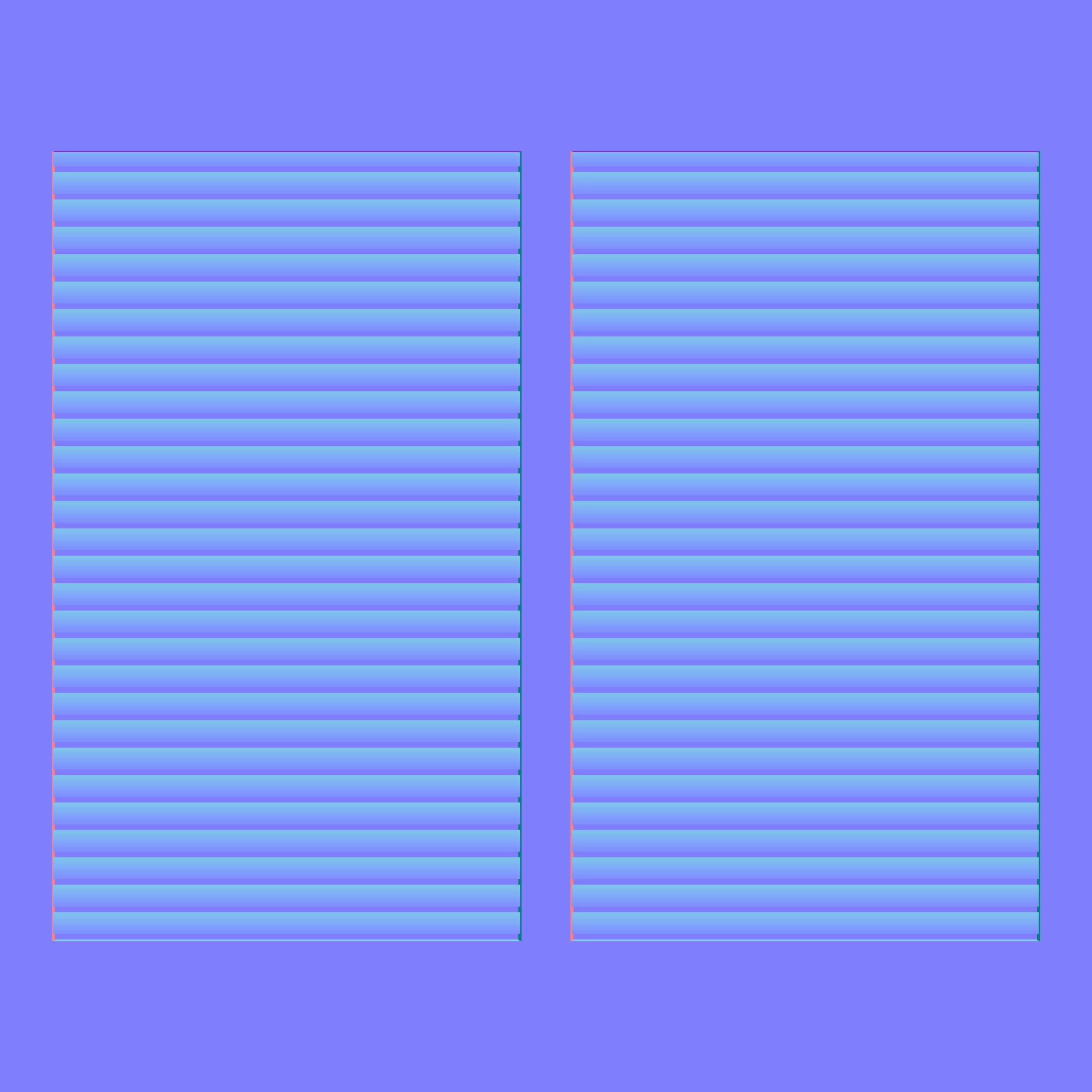
The detail of the vent will be faked with three images. These images, when added to a plane, will make the plane look like the vent meshes. The plane still will not have any color added to it or metallic properties. It will just look like the mesh, for now.
These three fake geometry PBR images are the normal map, the height map, and the ambient occlusion map. More information on what these maps represent can be found on the key concepts page.
Inputs
xNormal will use the three meshes you created in Blender
- the vent
- the vent background
- the plane
xNormal will also need two solid color textures
- red
- clear
xNormal Settings
High definition tab
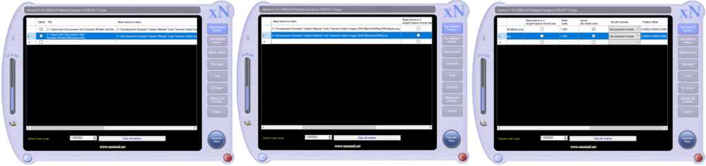
Select the High definition tab.
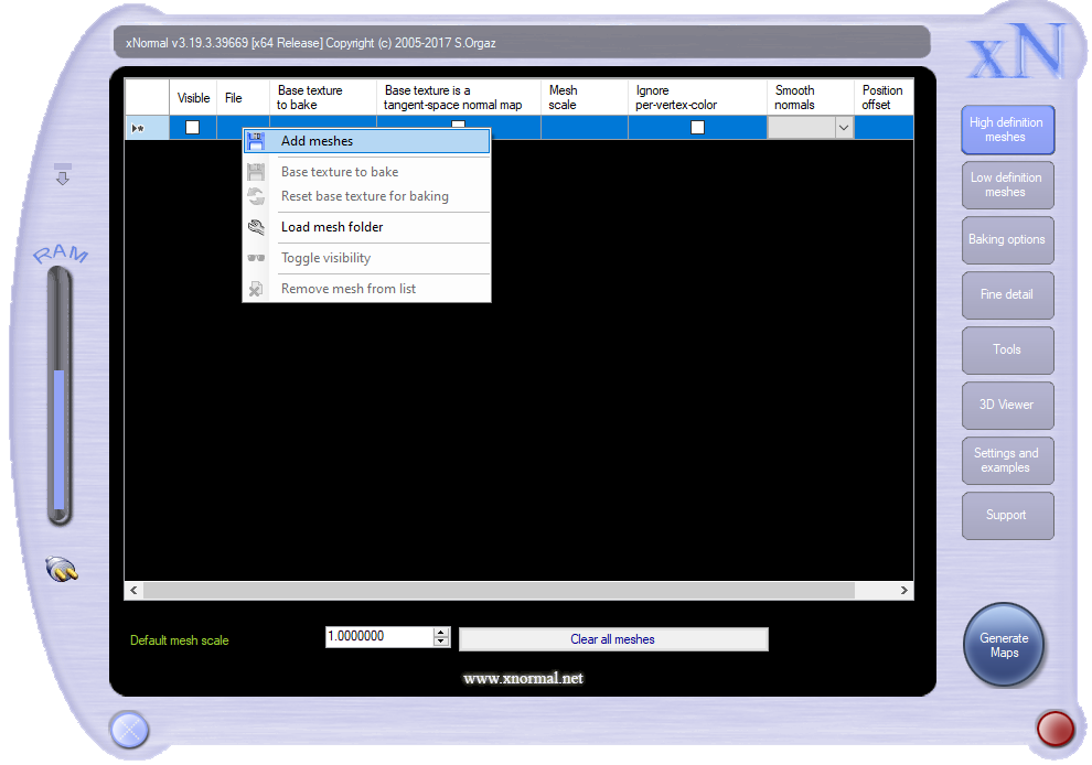
There are two input meshes, the vent (shell and grill together) and the background.
Right mouse click an empty row.
Selecting “Add meshes” from the dropdown menu.
Select the vent FBX file from wherever you unzipped the input folder.
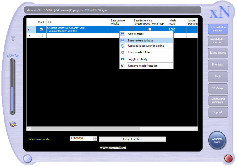
Now we will add a texture to the mesh.
Right-click a row with the vent object applied to it
Select “base texture to bake“.
We have two solid colored textures. One is red, and the other is clear. We are using these textures to create a mask texture. Our mask will have red in the pixels that our vent occupies and clear everywhere else.
Select the solid red texture from wherever you unzipped the input folder.
Repeat adding a mesh, this time the background FBX file from the input files.
Right mouse click an empty row.
Selecting “Add meshes” from the dropdown menu.
Select the background FBX file from wherever you unzipped the input folder.
Add the clear texture to the background object.
Right-click a row with the background object applied to it
Select “base texture to bake“.
Select the clear texture from wherever you unzipped the input folder.
Low definition tab
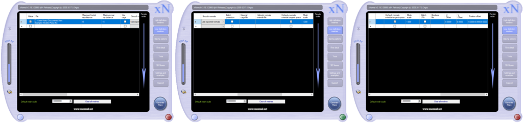
Select the low definition tab.
Add a mesh, choose the plane FBX file you exported from Blender. This mesh is added the same way as meshes are added in the high definition tab. Except, you do not add a texture to the low definition mesh.
Right mouse click an empty row.
Select “Add meshes” from the dropdown menu.
Select the plane FBX file from wherever you unzipped the input folder.
The Maximum frontal and Maximum rear ray distance settings will need to be adjusted based on your objects’ scale. That is the maximum distance from any location on your vent mesh to the closest location on your plane. The closest location is not just the vertices of the plane but anywhere on the plane.
Set Maximum frontal and Maximum rear ray distance to 15 (specific to this example).
Baking options
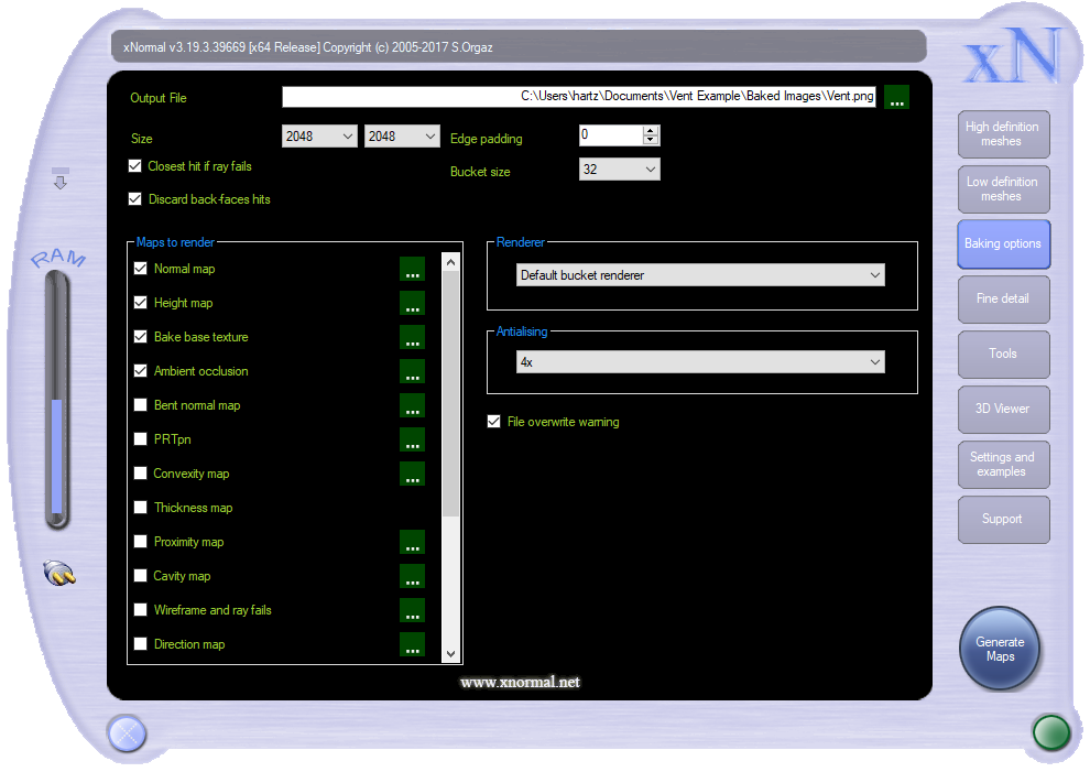
Select the Baking options Tab
In the Maps to Render section check the boxes:
- Normal map
- Height map
- Bake base Texture
- Ambient occlusion
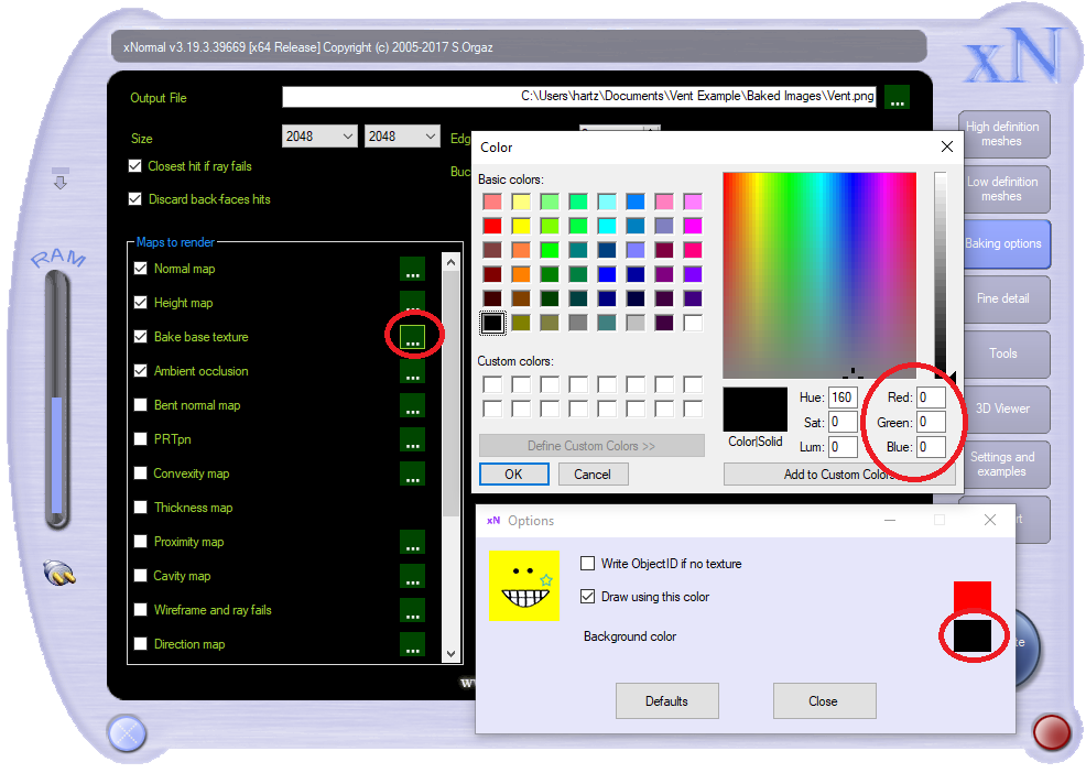
These are the Maps we will render. Bake base texture is the mask that required us to add textures to our High definition meshes.
Near the top of the window is an area labeled Output File. Choose an output file for all the maps you are creating. Each render will save as an output file with the file name you chose and the type of file being rendered added to the file’s name.
Set edge padding to 0.
Choose an anti-aliasing setting. I like having it set as high as it goes, 4x, to make the image less pixelated.
For this example, set the size to 2048 by 2048.
Maps to Render Options
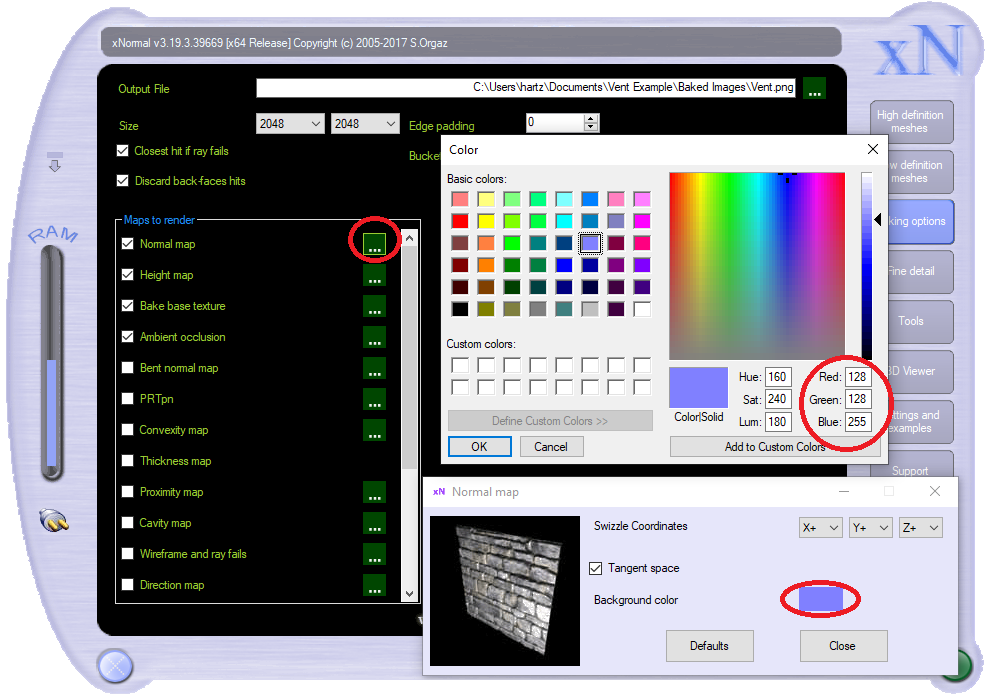
Each of the output image types you have selected in the Mask to render section has a set of options you can open by pressing a button with three periods on it. In this example, you will not need to adjust the options for your Maps to Render.
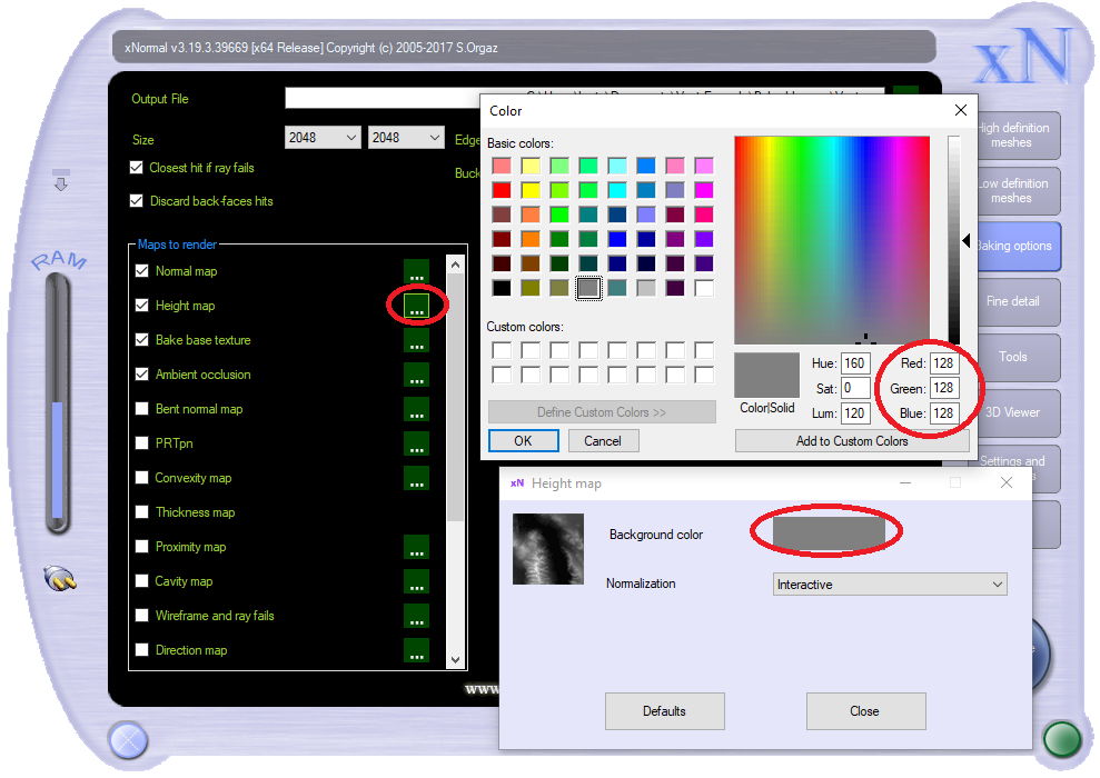
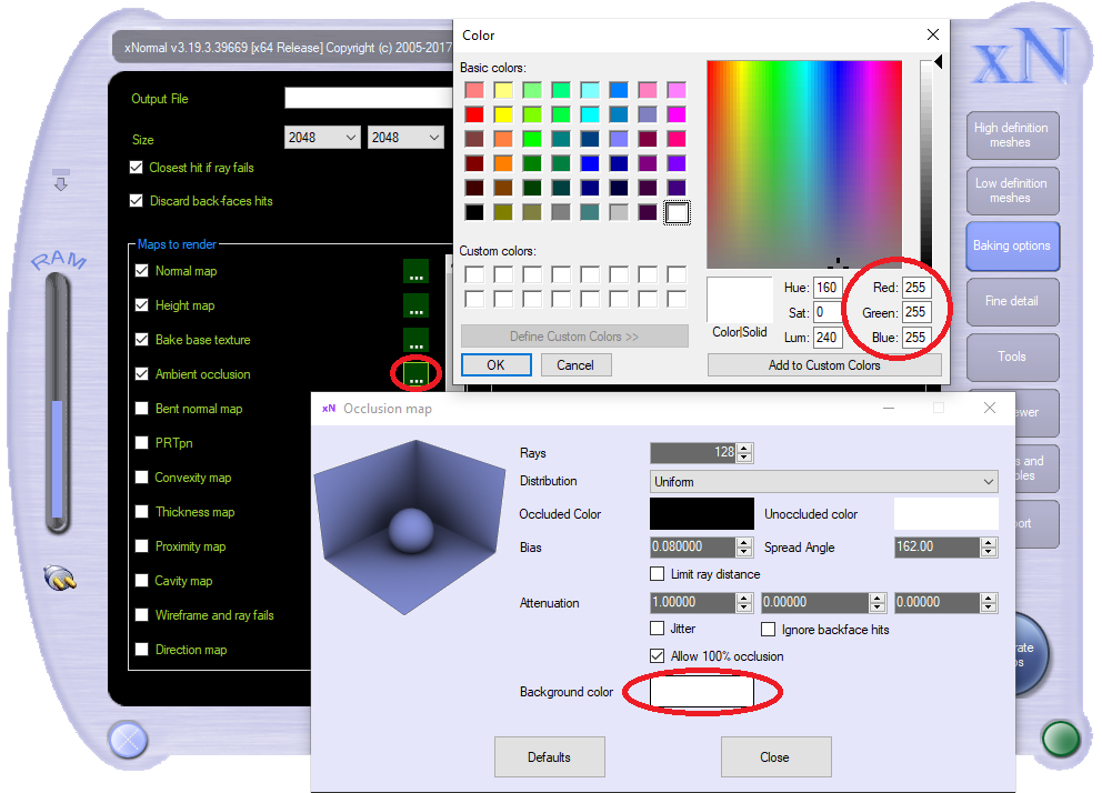
Background color is the option that you will most often use. All your pixels in the output images should map to locations on the high definition map. Background colors are only used when a pixel doesn’t have a high definition object within its ray casting reach. The images below show the default background colors of each output type.
I don’t change any of the other options.
Normal map options
Height options
Bake base texture options
Ambient occlusion options
Generate maps
We are now ready to Generate maps. Press the big Generate Maps button in the lower right corner of xNormal. A new window opens, and the maps begin to generate. If you are overwriting older images, xNormal will pause to ask you if you want to do this.
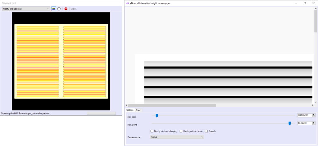
Height map pop up options
After the heightmap is generated, a window will appear where you can adjust the colors. I always do.
Choose values for the min value and the max value. Make sure the numbers are opposites, additive inverse. One is the negative of the other.
This trick avoids an artifact that is an eye-sore. If you make this adjustment edges of the image will have a neutral height value, 0.5, in every heightmap you create
This 0.5 value along the edges is important in all height maps, but more so in height maps used as baked decals. When we overlay the decal onto another image, the images will not blend smoothly into each other without the 0.5 value along edges.
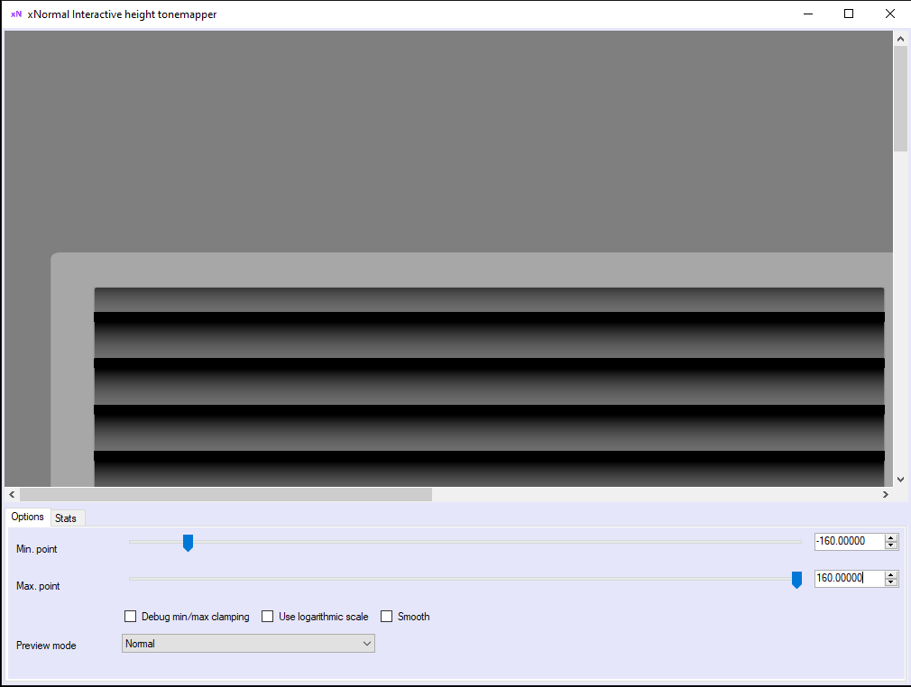
If you have two objects next to each other, like segments in a wall, the height values at the edges of the objects need to be the same. If the height values are not the same, a weird black line will show up at the seem. Good luck trying to adjust the height values manually if you don’t use this min and max value trick.
How high or low you want to set these min and max values will affect the contrast of light and dark in your heightmap. By default, the min and max values are assigned to the highest and lowest heights, but you can lose detail at one extreme or the other to gain detail in the middle. In most cases, I choose whichever value given by default that is further from zero, the max or min. Still, in this example, the negative value represents the back of the vent shell, and I am more interested in showing detail on the front and grill, so I chose a smaller value that I thought made the result look good.
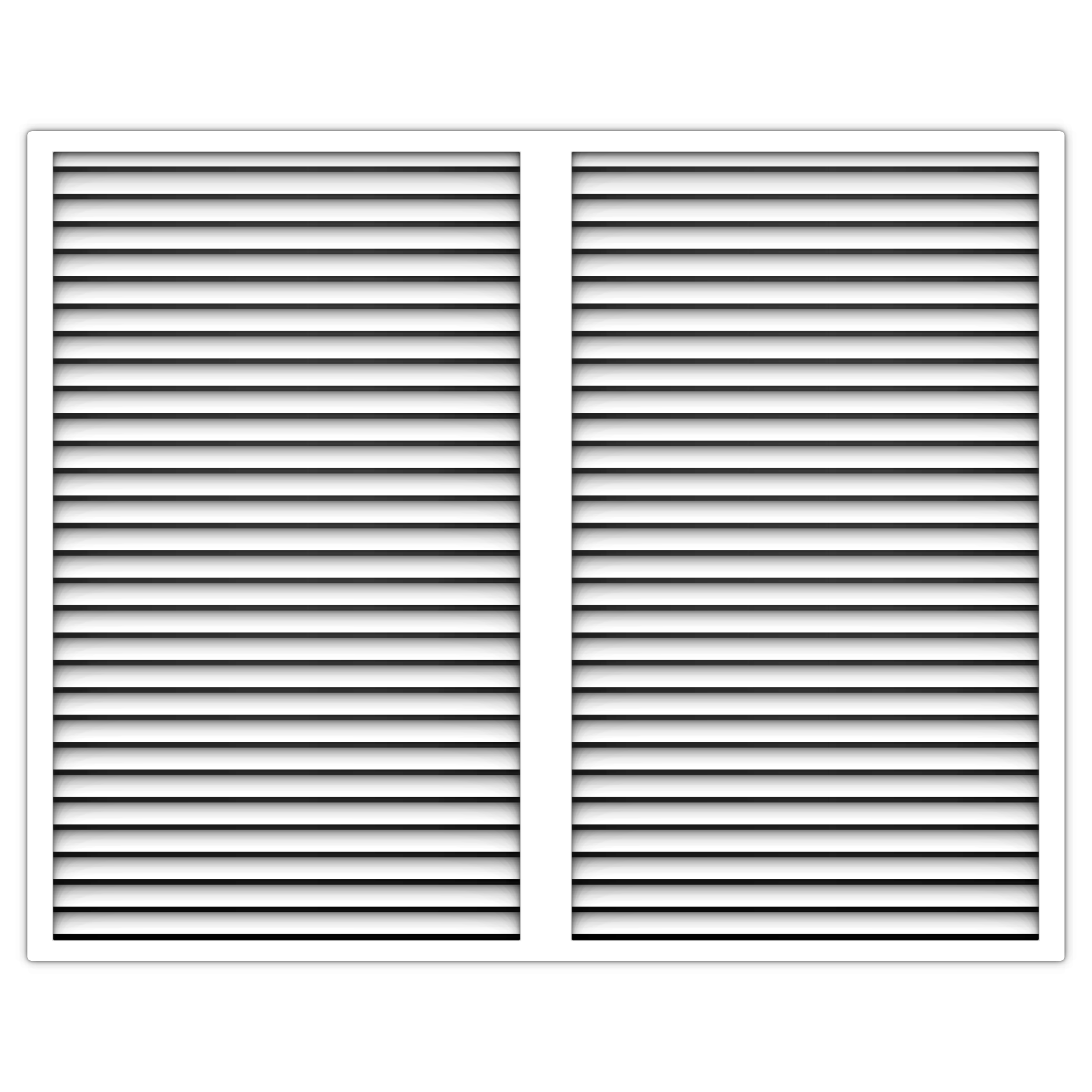
Output
Mask
Fake Geometry
Ambient
Occlusion
Height
Normal