This program is probably the most conceptually difficult to understand of the Material Tools programs. The input image itself is not being rotated like with the Rotate Flip Program. This program does something more abstract. It is, in a sense rotating the colors in the image. What does it mean to rotate colors in an image? A normal map is a tool for storing directional data, a normal vector. See Normal Maps in Key Concepts or a more extensive description. That directional data is what is being rotated. The directional data is just being represented as a color.
Think of each color pixel of an image as a little arrow. The direction the arrow points is based on the color of the pixel. If you rotate all the little arrows, so they face different directions, you change the colors that represent the arrows.

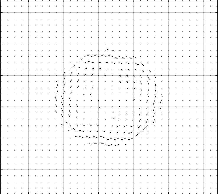

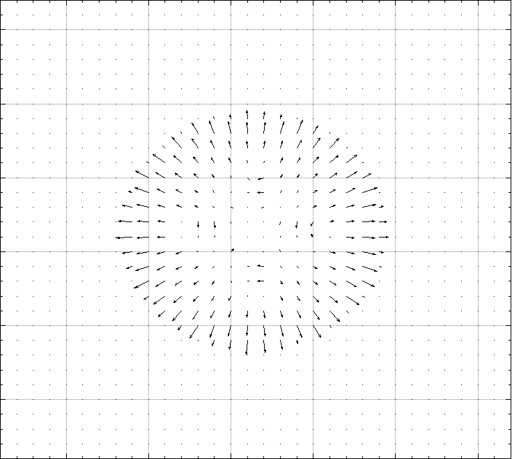
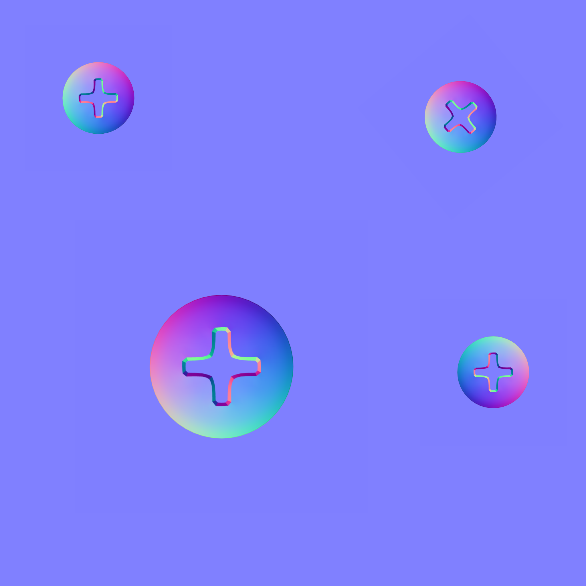
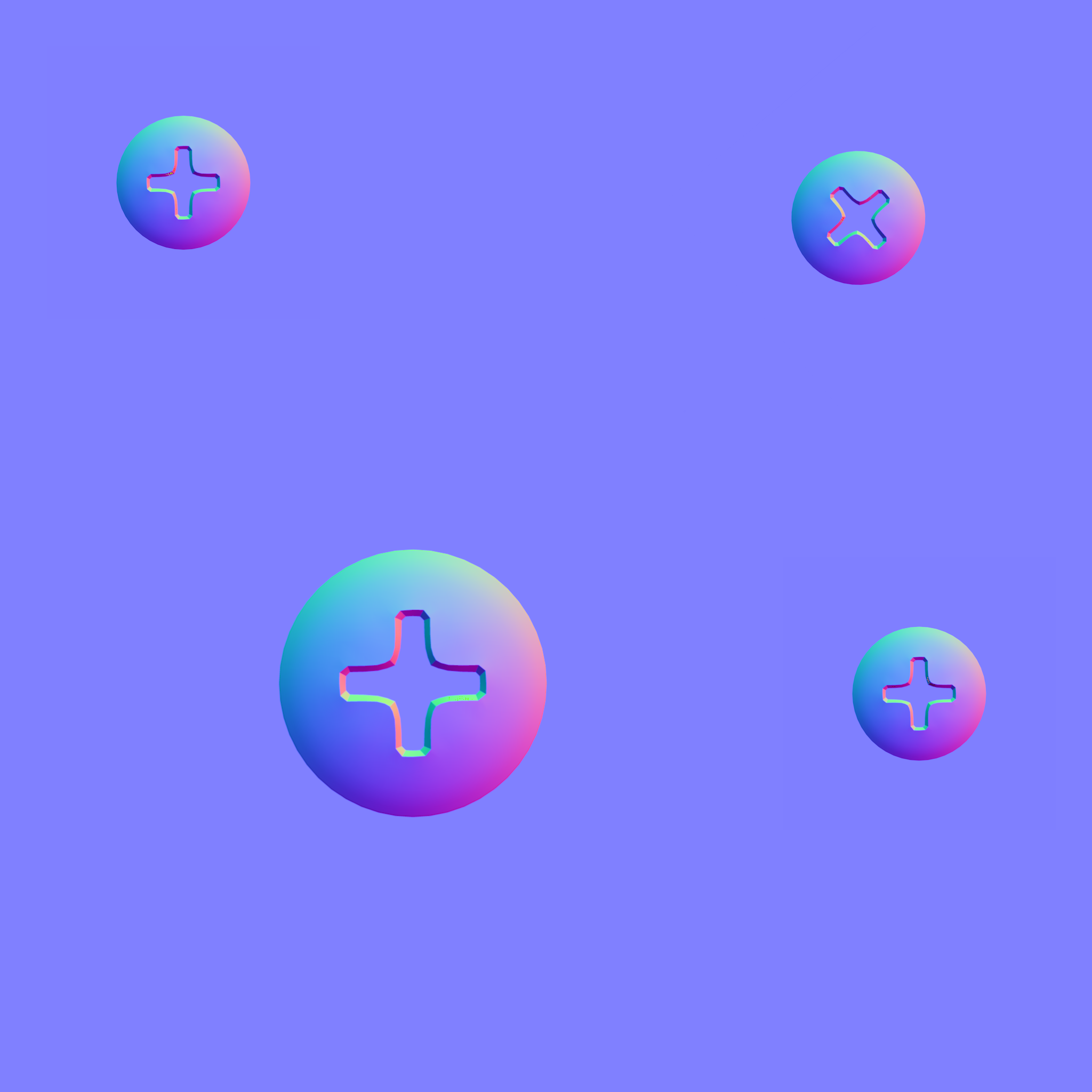
A representation of what rotating normal colors does. This example shows a vector representation of the normal map, and the vectors are individually rotated around the Z-axis (in this example, vectors are rotated 90 degrees).
A problem arises when the Normal map image is rotated or if a decal image baked into the Normal map has a different orientation than the Normal map it is baked onto. If this is the case, you get screwy reflections that shine from illogical angles as you move around your object in a scene.
Rotate Normal Color reorients the Normal Map’s reflection information by correcting the red and green color channels of the image. This correction is based on a rotational value that is either given by the user or calculated. If many decals with different orientations have been baked into the normal map, rotational values can be calculated for each decal. This operation requires an image I call a Baked UV Maps Image, created with the program xNormal.
Note: I explain how to do this in the Key Concepts/ Decal UV Orientation Map section of this website.
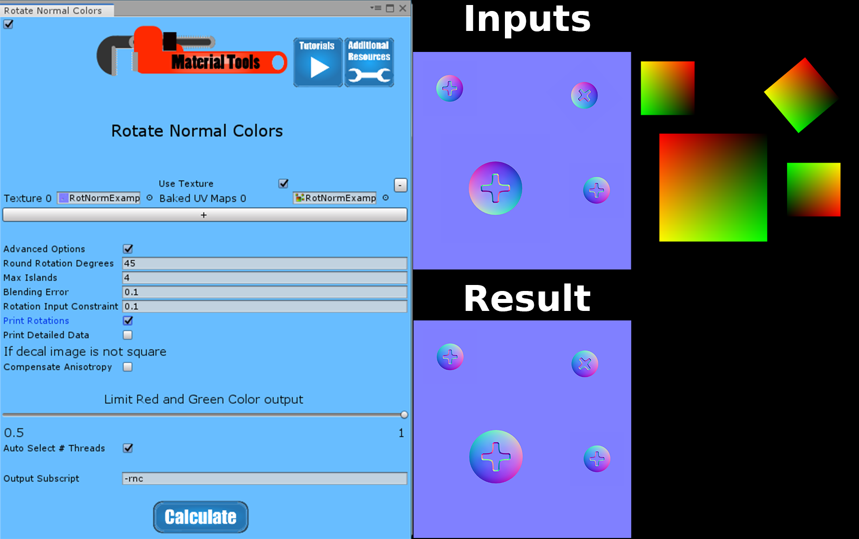
Example Normal Color Rotation
Input
Normal Texture
Baked UV Maps

Output
Options
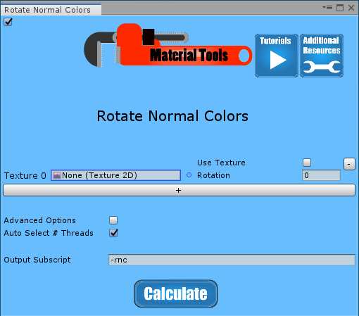
Texture
This is the normal texture that is going to be color rotated.
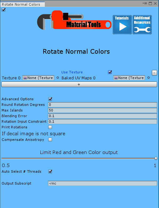
Use Texture
When this box is unchecked, the “Rotation” parameter input is visible.
If this box is checked, the “Baked UV Maps” parameter input is visible. This option calculates a separate rotation for every individual decal. Checking this option causes the program to take more time to run since you are adding many additional steps.
Rotation
This parameter is only visible when Use Texture is unchecked. The rotation parameter allows you to enter the angle, in degrees, to rotate normal colors.
Baked UV Maps
This parameter is only visible when Use Texture is checked. Baked UV Maps uses an image of baked UV maps to determine rotations for each decal baked into the normal map. These Baked UV Maps look like a sea of the color [0,0,0,0] (fully transparent) with a bunch of square islands with color gradients on each island.
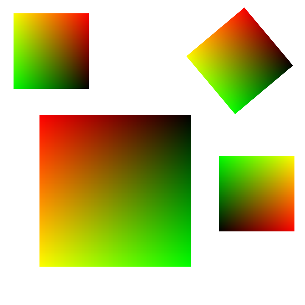
With this Baked UV Maps texture provided, the program uses an iterative process to identify each island. The orientation of each island is determined based on the color data in the Baked UV Maps texture, and a required rotation is calculated for each island. These rotations are used to adjust the normal map’s red and green color channels for the pixels contained within each island individually.
The process can take time depending on the size of the image and the number of islands.
+ and –
These buttons allow you to run multiple inputs at the same time.
Advanced Options
These parameters are only visible when Advanced Options is checked.
Round Rotation Degrees
This parameter is only is worth using with baked UV maps. It rounds the rotation for each island. After rotations are calculated for each island, rotations are rounded to the nearest multiple of Round Rotation Degrees. Then those rotations are applied.
Round Rotation Degrees is a useful way of eliminating minor errors from baking. The default value for this parameter is 0, no rounding. Suitable alternatives include 45, 15, 5 since they divide into 90 degrees with no remainder. Working with decals starts by placing them in a 3D modeling software, like Blender.
While placing your decals around your low polygon model in the 3D modeling software, only rotate the decals in rounded increments. You should plan ahead and use round numbers for your rotations when placing decals. You can then get exact results when you rotate normal colors using the Round Rotation Degrees Parameter.
Note: Some baked decals may have 90, 180, 270-degree rotations from unwrapping alone, even if you didn’t rotate any decals when you placed them in the 3D modeling software.
Max Islands
This parameter is only used with baked UV maps. It represents the maximum number of iterations in the island finding operation. This value should be larger than the total number of decals being baked into the image, but the larger this parameter is, the longer the program takes to run. The program is designed to quit out once all the islands are separated. Still, the baking process sometimes creates small artifacts that the program misidentifies as islands that can extend the calculation. These tend to be separated last, so a lower island value ignores these artifacts rather than actual islands.
The default value for this parameter is 50 islands. This value is one you often changed to fit your image and its number of decals.
Rotate Input Constraint
This parameter is only used with baked UV maps. It is very technical and has to do with balancing the accuracy of finding an island’s rotation with the flexibility to choose less ideal pixels for calculation when there aren’t any better choices. The default value usually works fine, but you can increase it slightly if you are getting entirely wrong island rotations.
Small numbers give a more accurate result, but if they are too small, the result is entirely wrong.
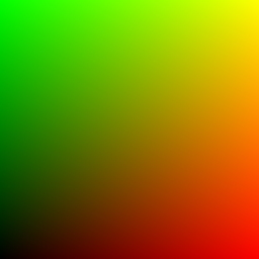
Rotation is calculated by comparing the line’s slope from the black to yellow in the UV image to the slope that line would have if the UV image were not rotated. In an image that has not been rotated, this line has a slope of 1. This parameter controls how closely pixels have to come to the black-yellow line to be considered for island Min and Max values.
Because baking averages pixels together and rotating a raster image in increments other than 90 degrees adds some inaccuracy from what you would expect from a continuous field of values. Increasing the value of this parameter gives a degree of wiggle room when no pixels meet the desired criteria.
What is meant by the black-yellow line? A UV image gradually increases from [0, 0, 0, 1] in the bottom left corner to [1, 0, 0,1] in the bottom right corner, [0, 1, 0, 1] in the top left corner, [1, 1, 0, 1] in the top right corner. The black, yellow line is a theoretical line running from [0, 0, 0, 1] to [1, 1, 0, 1] or from the bottom left corner to top right corner, and has a slope of 1 in a UV image that has not been rotated. If this line’s slope is not equal to 1, the UV map has been rotated, and you can use the slope to figure out how much the UV map has been rotated and how far it needs to be rotated back to get a slope of 1. This rotation value is the same rotation you will apply to the normal red and green channels.
This parameter’s default value is 0.01, which is small enough to select pixels close to the black, yellow line while allowing for inaccuracy due to pixel averaging performed in the baking process. This value can be increased if the image uses small decals and images with non-90-degree rotations or combinations of the two.
Blending Error
This parameter is only used with baked UV maps. It represents the minimum alpha value (opacity) a pixel must have to be considered for this program’s calculations. Pixels with lower alpha values are caused by averaging pixels from the decal and background clear pixels representing empty space with no data. These mixed data and no data pixels provide no useful data and corrupt the process of determining island orientation if they are not excluded from the calculation.
The background color of the baked for Decal UV Orientation Map must be clear, so no data areas are being confused with black pixels. The lower-left corner of a UV map is black, and this region is important for this calculation. Decals should be created to have a border region that can be easily excluded without losing any useful data to account for averaging in the baking process colored [0.5, 0.5, 1, 1]. This color of a normal map representing a flat surface following the model geometry.
This parameter’s default value is 0.1, meaning the red or green value must be larger than 0.1, or alpha must be greater than or equal to 0.9 for the pixel to be considered for the calculation. The value 0.1 is small enough to exclude most pixels that have been averaged with transparent pixels in the baking process.
Print Rotations
This parameter is only needed with baked UV maps. It prints calculated rotations to the console.
Baked in decal images do not have square dimensions
This parameter is necessary when decals are not square. The math to calculate the rotation is slightly more complicated with non-square images.
Limit Red and Green Color Output
This parameter sets a cap on how far red and green values can be from 0.5. Putting this cap flattens out the extremes in apparent geometry.
Limit Output Intensity can fix impossible or exaggerated normal values when mixing with a low Decal Fade and a high Base Blend on Decals. In such cases, Limit Output intensity by default smooths out values higher than 1, and Auto-Correct Normals scale down evenly red and green channel values until they fit the ideal normal function. See Normal Maps in key concepts.