PBR Materials
Physically Based Rendering (PBR) uses additional images other than an object’s color. These images describe the reflective properties of the object and small scall geometry information.
High polygon and decal geometries can be represented on a low polygon object by utilizing a PBR material.
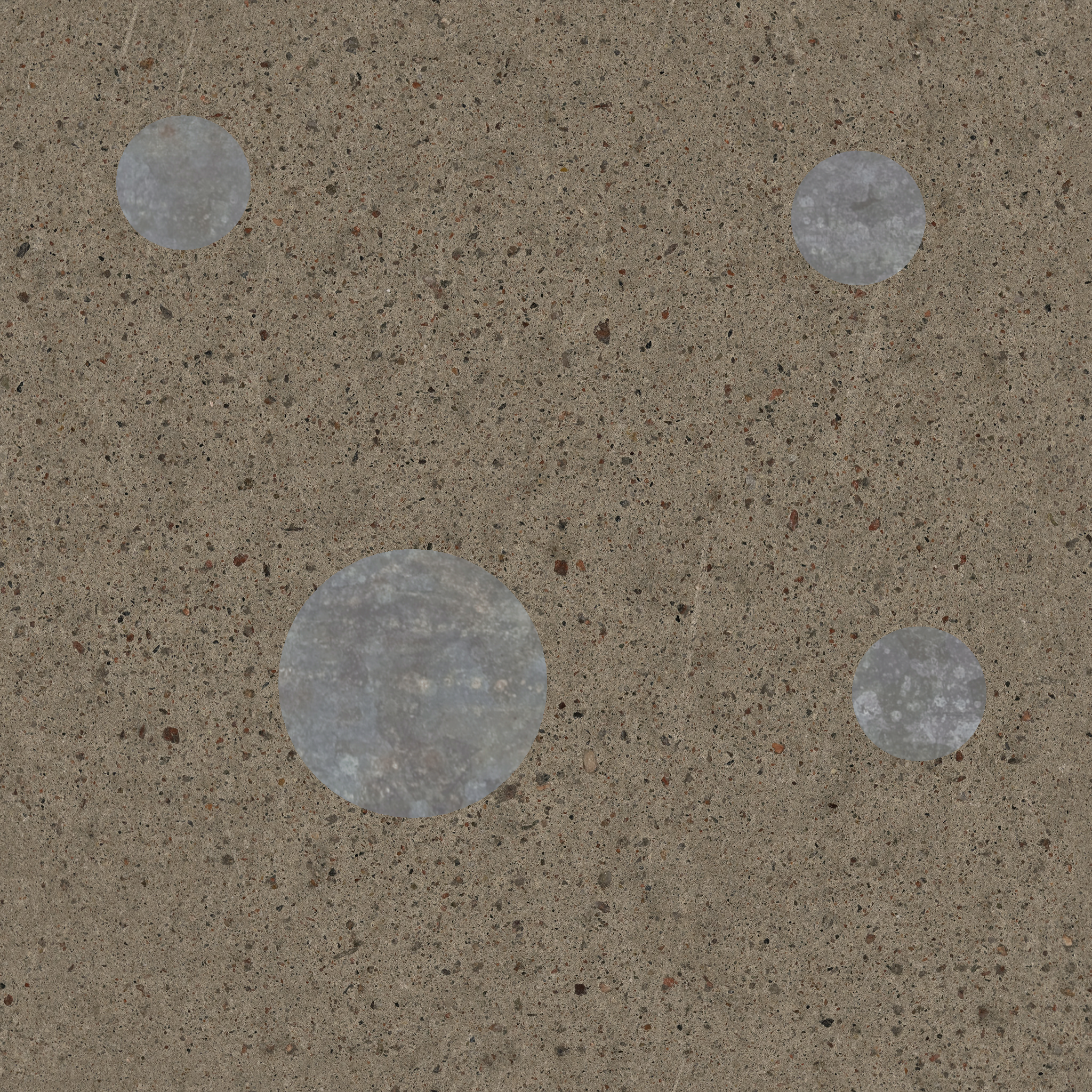
Albedo Maps
These images contain basic color information of an object without considering shadow or reflections.
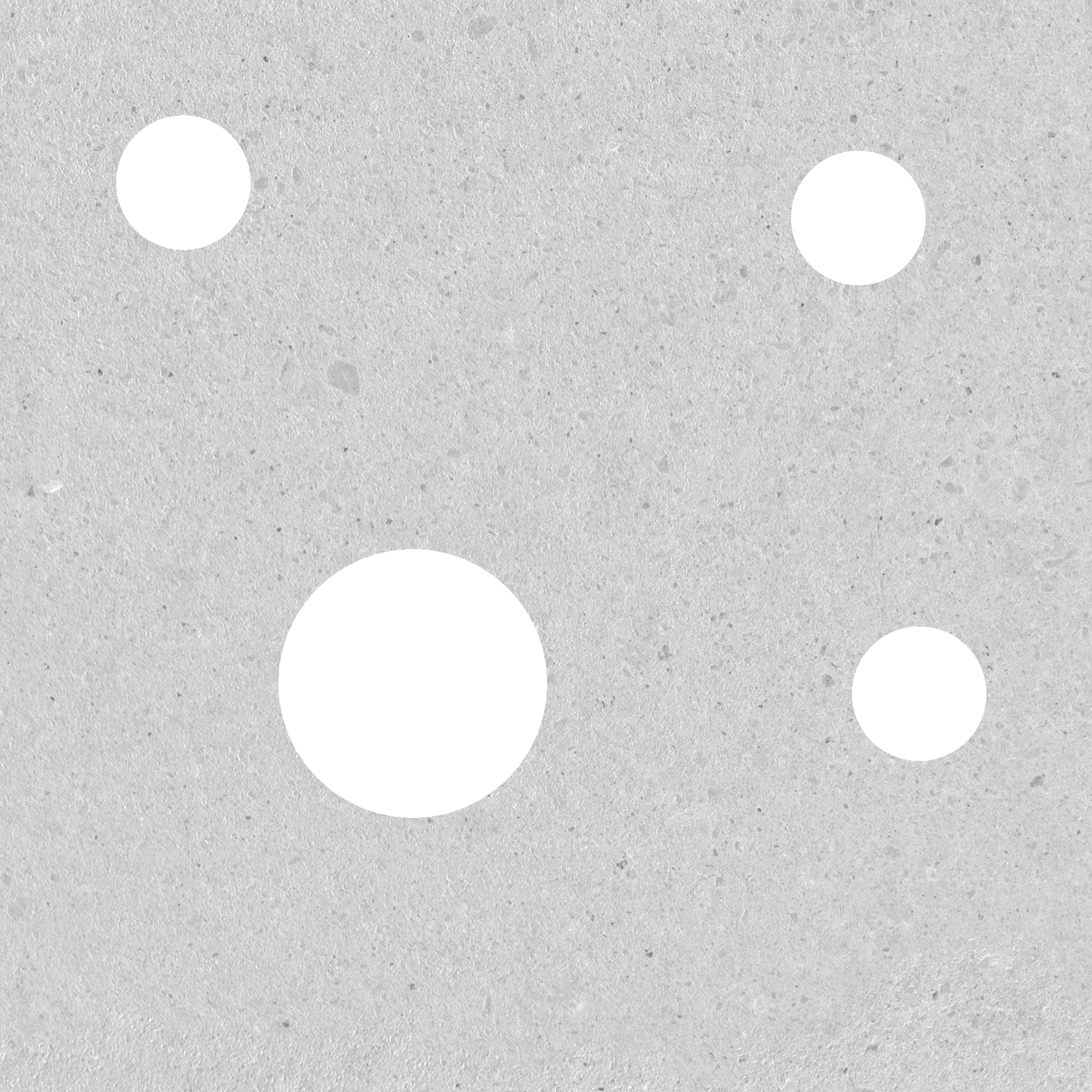
Ambient Occlusion Maps
This map displays shadows cast by an object upon itself under ambient lighting conditions. It has the effect of shadowing crevices and recessed areas. This map is typically white, with shadowed areas appearing as grey to black depending on the fraction of ambient light they receive.
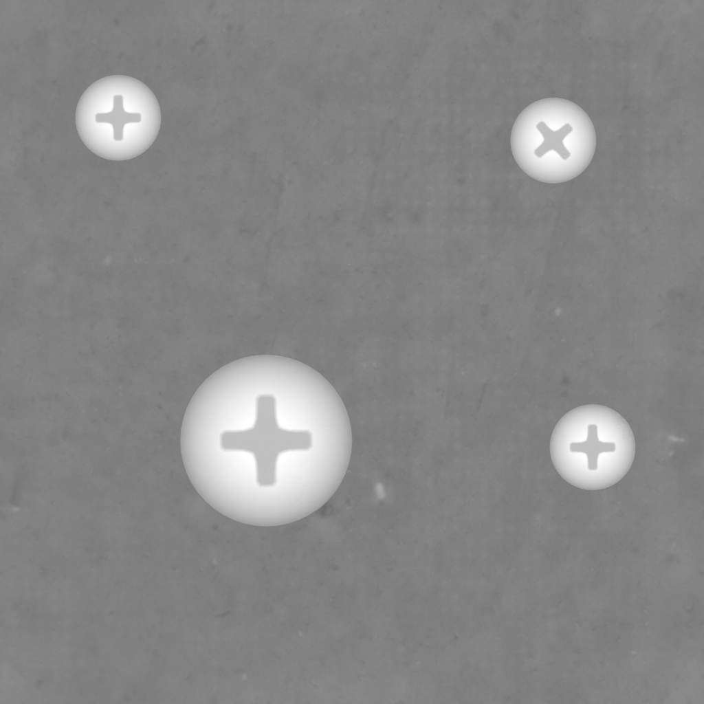
Height Maps:
Height Maps are a way of passing geometry data to a material to cause apparent depth changes. Height Maps have a base value of 0.5 ([0.5, 0.5, 0.5, 1]). Values above 0.5 look like they are sticking out of the object. Values below 0.5 look like they are indented into the object.
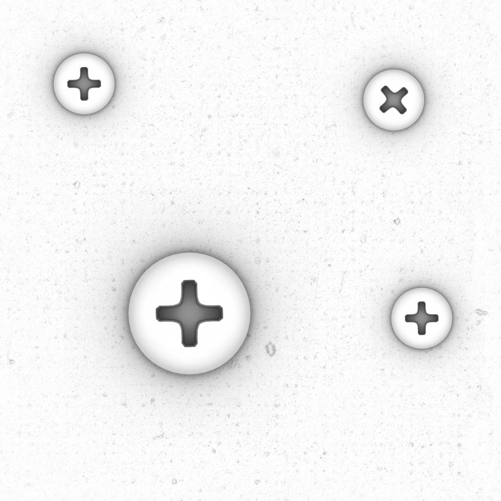
Metallic Maps:
Metallic maps measure two things Metalness and Smoothness. Metalness stored in the r, g, and b channels, all three channels having the same value. Smoothness is stored in the alpha channel. Metalness is 1 if metallic and 0 if not. In between values tend to represent a visual averaging due to subtle details that are hard to make out. Like painted metal where many little spots of paint are flaking off, but you can’t see them well.

Note: This image only looks grey because it is semi-transparent. Often it isn’t easy to visualize the alpha channel (opacity) of these images. A trick is to use the Append Color Channels tool to create an image of the alpha channel to see what is going on.
Why do we use metalness? Metallic and non-metallic substances reflect differently. If you want to dig into the physics behind this, the keywords to look up are conductor(metals), dielectrics (non-metals), and Fresnel Reflectance.
Smoothness is 1 for a perfectly smooth surface and 0 for a perfectly rough surface.
Normal Maps
: Normal maps are used to fake geometry by causing reflections to occur at angles represented by the Normal Map. The default color of a normal map is [0.5, 0.5, 1, 1], representing geometry matching the underlying 3D model.
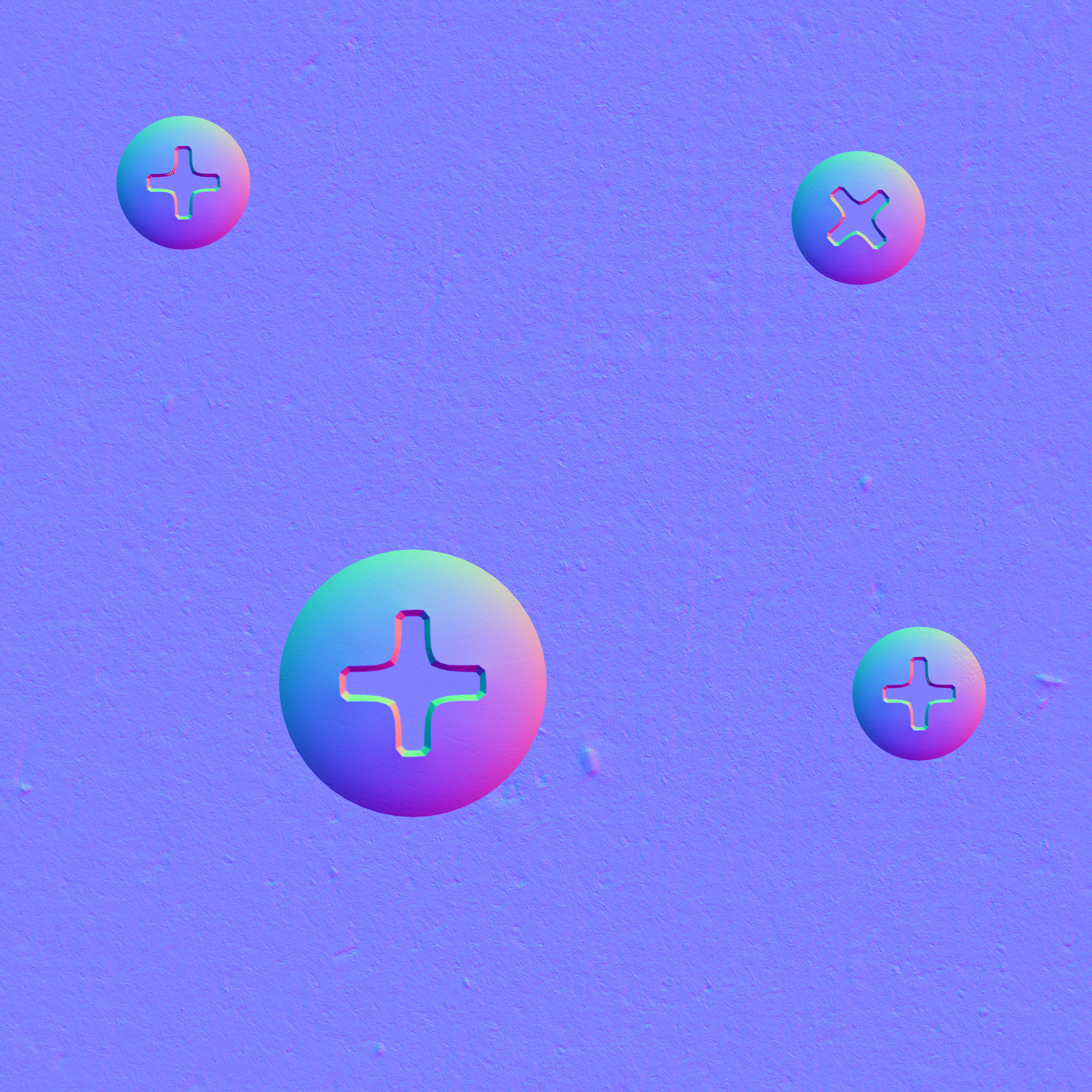
In a normal map, the colors red, green, and blue represent faked geometry orientation. The normal map causes reflections to appear as if there is a bend or corner in the model. Most of the PBR textures make this faked geometry look real, but their color information is not related to direction like a normal map is.
- [0, 0.5, 0.5, 1] This represents the faked geometry is tilted 90 degrees to the left of what the model Specifies.
- [1, 0.5, 0.5, 1] This represents the faked geometry is tilted 90 degrees to the right of what the model specifies.
- [0.5, 0, 0.5, 1] This represents the faked geometry is tilted 90 degrees down from what the model Specifies.
- [0.5, 1, 0.5, 1] This represents the faked geometry is tilted 90 degrees up from what the model Specifies.
Normal Maps follow a mathematical formula. To understand this relationship, you must first convert from the data values stored in the image ranging from 0 to 1 to the mathematical space used by normal maps -1 to 1. This conversion is:
X= 2r-1,
Y= 2g-1,
Z= 2b-1.
Now the functional relationship between these converted colors is the equation for a unit sphere:
X2+Y2+Z2=1
Also, negative Z values have no physical meaning, so:
Z >= 0
Faked Geometry
I use this term to describe the effects of Ambient Occlusion, Normal, and Height textures. In a PBR texture, the combination of these three texture cause visual effects that appear to be additional geometry in a model. The 3D model does not include this faked geometry.
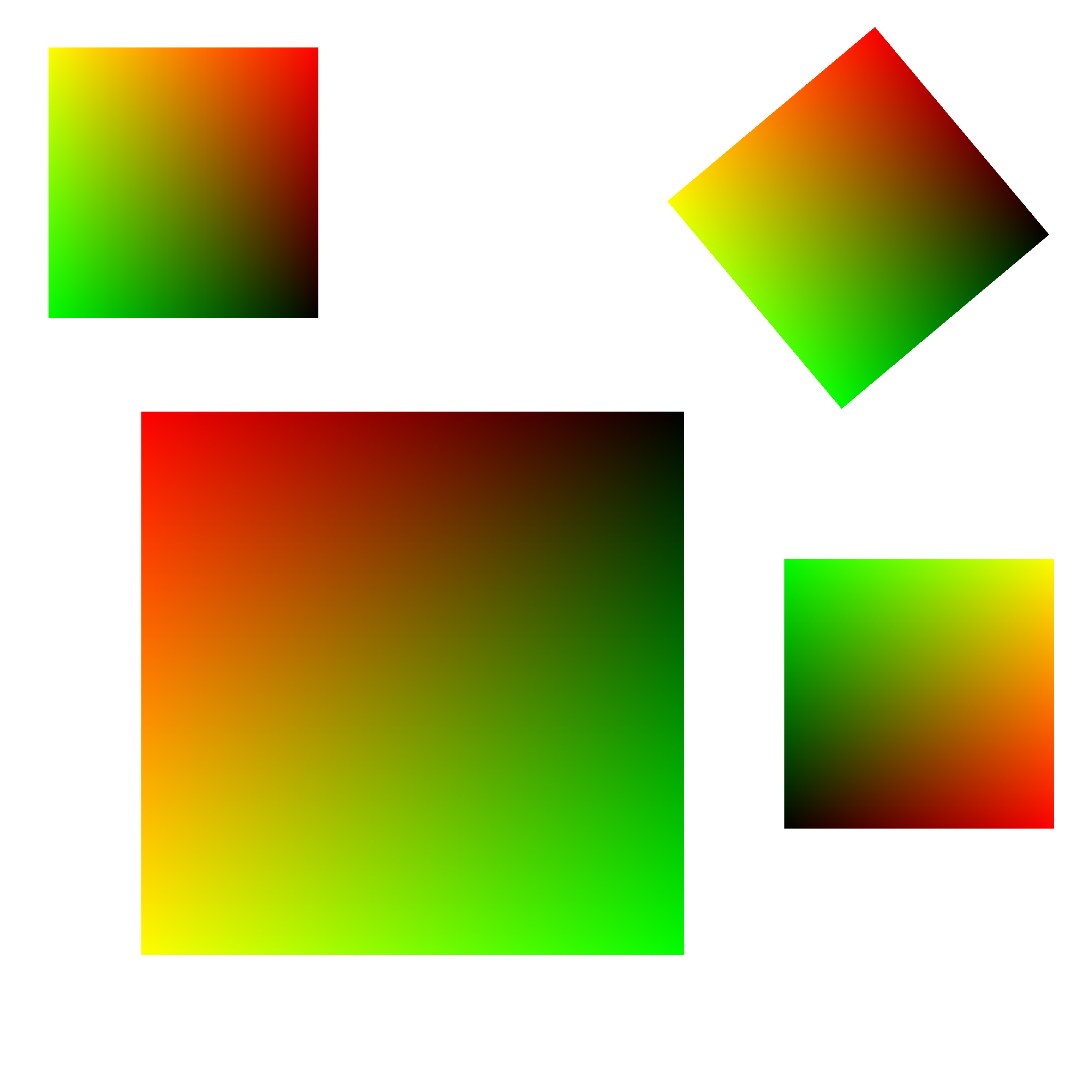
UV Maps
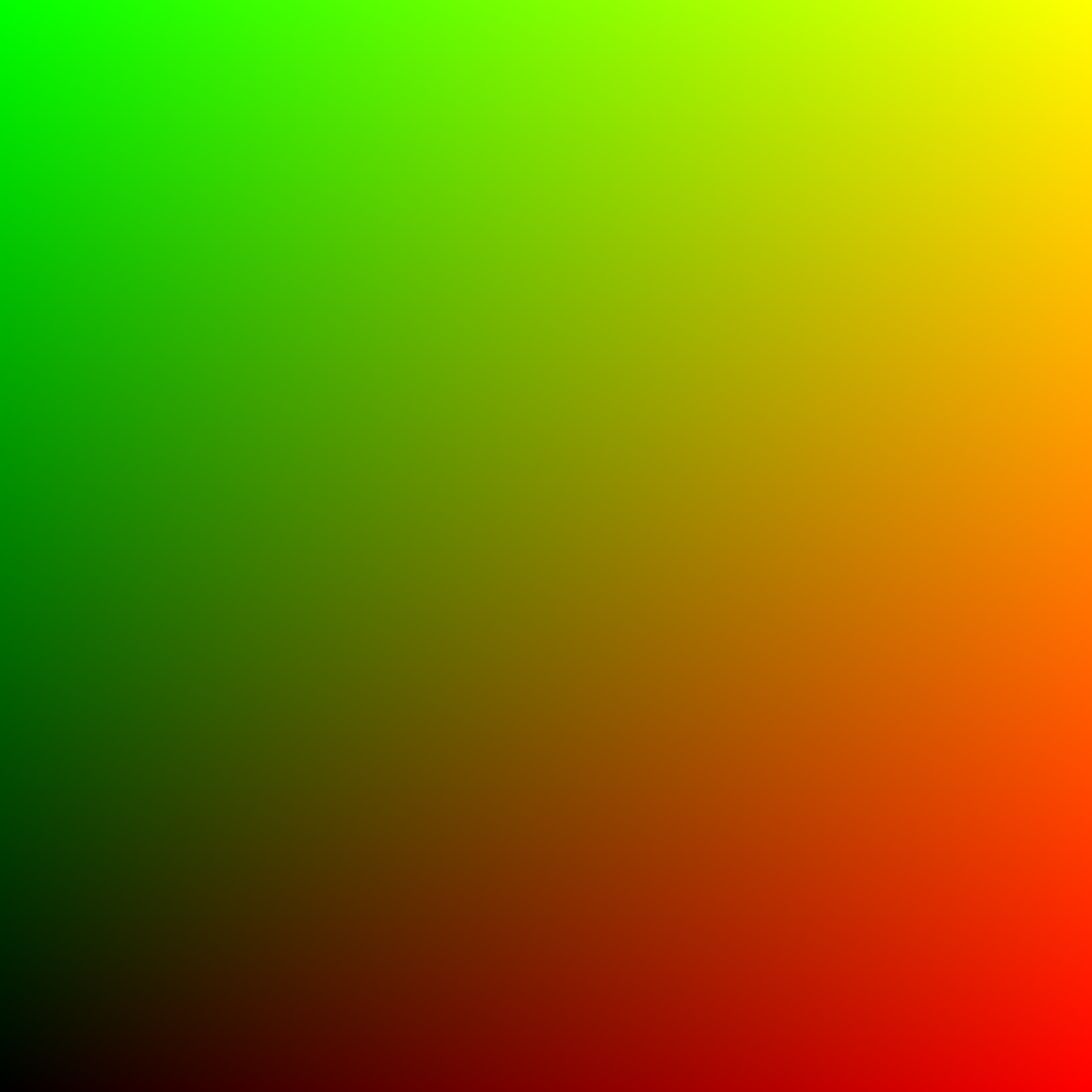
Baked UV Maps:
If you haven’t heard of Baked UV Maps, that’s because I made it up for this process. Baked UV Maps are a baked image with the low polygon mesh of your model, the high polygon meshes are your decals, and their associated images are all a standard UV Map. You end up with a clear image with a bunch of little UV maps scattered around it. Some of these little UV Maps may be rotated.
Parallel Threads
Running parallel threads allows a program to run multiple methods at once using separate CPU cores. In the case of Material Tools, it will enable your computer to use the same method on a different set of inputs concurrently. Your list of work is completed faster because it puts more of your processing power to work. Most of the Material Tools programs use the same parallel thread method. This method uses a minimum of 2 threads, the main thread, and as many child threads as specified with the Num Threads parameter.
The main thread deals with loading textures, clearing textures from memory, starting threads, managing the batch’s progression, managing outputs from threads, and writing textures as png files to your hard drive.
The child threads do all the program-specific calculations that produce your desired output.
Correct Normal Colors
This method is used in many of the Material Tools programs. It scales down red and green channels if, in combination, they are too large to fit the function for ideal normal map values (unit sphere where Z>= 0) and recalculate the blue color channel of a normal map based on the red and green color channel values. Ideally, the color channels of a normal map should match that mathematical relationship.
X2+Y2+Z2 = 1
X = 2r-1,
Y = 2g-1,
Z = 2b-1
r is red in values 0 to 1,
g is green in values 0 to 1,
b is blue in values 0.5 to 1.
This parameter recalculates blue values to match this relationship. Note The Shadow Normals program intentionally breaks this relationship but does so for a good reason.
xNormal:
This is a free program for baking textures using a low polygon model, high polygon model(s), and textures. It is often necessary for making input textures for The Rotate Normal Colors Tool.
Decals
Decals are textures of all PBR texture types used as a part of a larger object’s texture. You can use them to add smaller details to an object’s Material. Adding PBR Decals to a material is a little complicated.
Blender:
This free 3D modeling software is as good as paid products like Maya and 3DMax.
A 3D modeling tool is needed to create baked decals and baked UV maps. You need it to create and position planes or quad objects where you want the decals to be located. After you export these objects as obj files, they can be used in xNormal to bake the images.